Full-Service Oilfield Maintenance and Compliance
Powered by Proven
Burner Management Systems
Pioneering Energy Solutions
West Texas
Table of Contents |
Reliable Oilfield Services: Precision, Efficiency, and Industry-Leading Preventive MaintenanceOilfield operations demand reliability, safety, and efficiency; and Reliable Oilfield Services (ROS) delivers. Whether optimizing burner management systems (BMS), conducting Preventative Maintenance (PM) on fired equipment, or managing new construction installations, ROS sets the benchmark for operational excellence. Even in locations without cellular coverage or Internet access, your SmartPhone or Tablet will connect effortlessly. The ROS BMS has its own built-in Access Point WiFi server, showing up as a local WiFi network you can log into directly, no external infrastructure required.Advanced Burner Management Solutions: Efficiency Meets InnovationMajor operators will benefit from ROS Burner Management Systems (BMS) to enhance the performance of their flares, combustors, and heater treaters. These advanced controllers streamline combustion efficiency, reducing downtime, emissions, and operational costs while ensuring regulatory compliance.Key Benefits of ROS BMS:
Comprehensive Preventive Maintenance: Maximizing PerformanceROS provides monthly, quarterly, and bi-annual Preventative Maintenance (PM) services, ensuring uninterrupted operation of critical equipment. Whether performing site inspections, flame tuning, or firetube cleaning, ROS ensures optimized combustion efficiency, minimized emissions, and extended equipment lifespan.Key PM Services:
New Construction Installations: Turnkey Solutions for EfficiencyROS specializes in new construction installations of flares, heater treaters, combustors, and flame arrestors, delivering pre-tested, ready-to-deploy solutions for high-performance operations.Installation Features:
ROS ensures that every installation is executed with precision, reducing startup delays while optimizing operational reliability. Driving Industry ExcellenceReliable Oilfield Services' integrated approach combining Preventive Maintenance (PM), Burner Management PM, Flare PM, Combustor PM, Heater Treater PM, Arrestor PM, heater treater firetube cleaning, flame arrestor cleaning and inspection, site inspections, and flame tuning sets a new standard for oilfield performance and safety. Operators can depend on ROS BMS controllers and PM services to:
For more details on Reliable Oilfield Services' Preventive Maintenance, BMS controllers, or new construction installations, contact ROS today. |
Burner Management SystemThe ROS Burner Management System (BMS) represents a cutting-edge solution tailored specifically for oilfield applications, including flares, heater treaters, and combustors. This advanced control system is engineered to enhance operational safety and efficiency. Features1. State-of-the-Art Technology:The ROS BMS utilizes innovative technology that meets industry standards, ensuring reliable performance for critical combustion operations. Designed with the complexities of the oil and gas sector in mind, this controller facilitates precise management of burner systems.2. Advanced Wi-Fi Capabilities:With robust Wi-Fi connectivity, the ROS BMS empowers operators with the ability to monitor and manage system performance remotely. This feature significantly reduces the need for on-site presence, allowing for timely interventions and streamlined operations.3. Real-Time Monitoring and Adjustments:Operators can connect to the ROS BMS seamlessly using their cell phones, tablets, or laptops. This functionality enables real-time access to vital system data and performance metrics from virtually anywhere.Users can make immediate adjustments to burner settings, monitor operational parameters, and receive alerts about system anomalies, facilitating proactive management and enhancing safety protocols. 4. User-Friendly Interface:The controller is equipped with an intuitive interface that simplifies navigation and configuration. Whether accessed via mobile devices or a desktop, operators can easily understand system status, historical data, and performance analytics, making it easier to optimize operations.5. Enhanced Safety Features:The ROS BMS integrates advanced safety mechanisms to monitor parameters such as temperature, pressure, and emissions. Should any readings exceed predefined thresholds, the system automatically triggers alarms and alerts to the designated operators, ensuring prompt corrective actions.6. Scalability and Integration:The system is designed to be scalable, allowing for integration with existing infrastructure. Whether it's a single unit or a large facility, the ROS BMS can be customized to meet the specific needs of various operations within the oilfield.7. Data Logging and Reporting:The BMS continuously logs operational data, enabling detailed reporting and analysis. This data can be essential for compliance audits, performance reviews, and continuous improvement initiatives, contributing to overall operational excellence.8. Transformative Tool:The ROS Burner Management System (BMS) is a transformative tool for oilfield operations, offering unparalleled remote monitoring and management capabilities. By enabling real-time access to vital data and the flexibility to make adjustments through personal devices, this system ensures that facilities maximize safety, efficiency, and compliance in managing combustion processes. Investing in the ROS BMS means positioning your operations at the forefront of technology in the oil and gas industry.9. Heater Treater Oil Water Separator:The ROS BMS supports Oil Heater Treater operations, which involve breaking water emulsions in the oil phase to achieve higher oil purity. This process typically follows at least one stage of separation, and may include a second stage. |
Burner Management System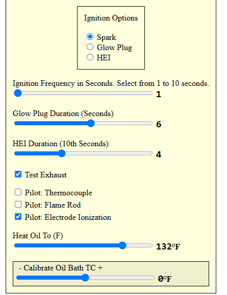 |
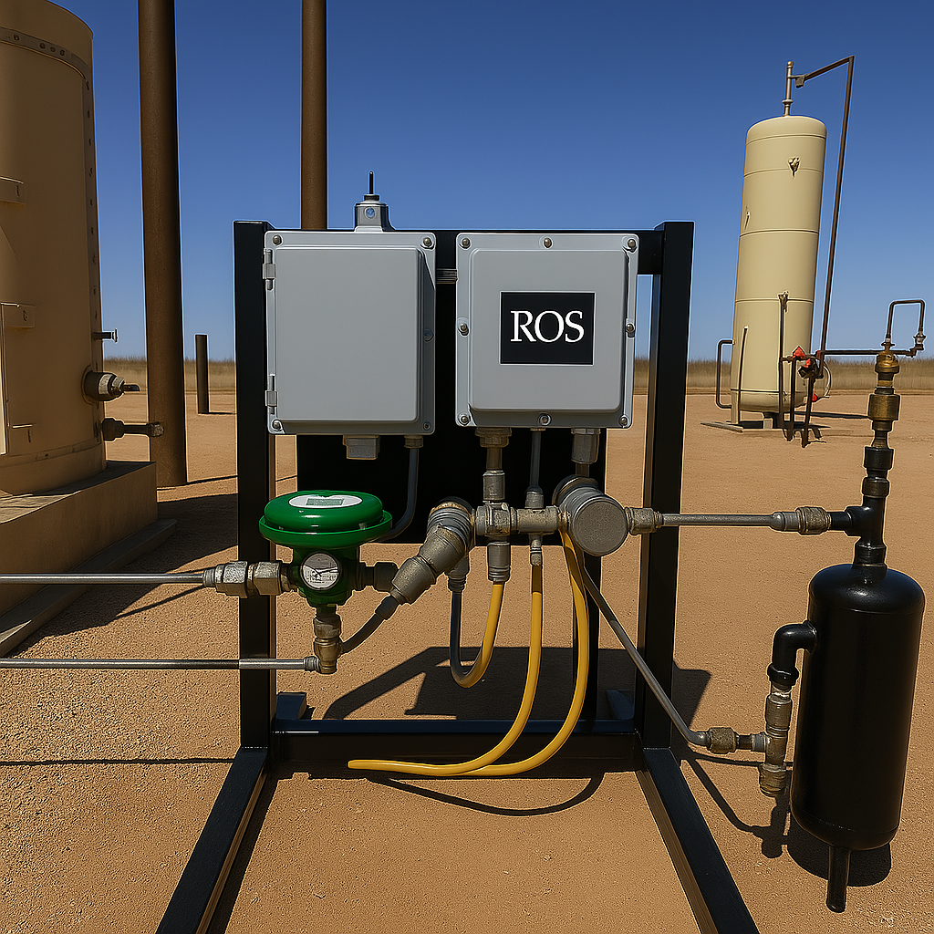
Waste Gas Flare StackROS BMS Flare Control DescriptionOverviewThe Reliable Oilfield Services (ROS) Burner Management System (BMS) is a Wi-Fi-enabled controller designed to manage flare igniters in oilfield applications, proudly Made in America. As one of the only American-made and manufactured controllers, it ensures a reliable supply chain, supporting operational continuity. The BMS, the first Wi-Fi-enabled system of its kind in the Permian Basin, provides remote monitoring and control via a smartphone, tablet, or laptop, enhancing safety, precision, and efficiency. The unit can be customized for specific flare requirements, ensuring tailored performance for diverse oilfield needs.BMS Controller:Housed in a UL-certified NEMA 4X enclosure, RoHS-compliant, with dimensions of 12in x 12in x 7in and a weight of 4 lbs.Powered by a 12V or 24V DC supply, suitable for oilfield conditions (-4°F to 140°F).
Flare Ignition SystemSupports multiple ignition methods:High Energy Ignition (HEI) for flares, ignition coil, or glow plug for specific conditions (e.g., high condensate locations).Pilot fuel is controlled by Gas Valve 1, which sends gas to the flare pilot to be ignited. The pilot can be monitored via a pilot monitoring system for real-time status updates. Flame Sensing:Utilizes thermocouples, flame rods, or electrode ionization for flame detection.Provides real-time feedback on flame status (e.g., Spark Electrode Ion, Flare Flame Rod Ion). Communication and Interface:Wi-Fi network (default password: 12345678) enables access to a user-friendly, single-page interface for monitoring and configuration.Control ProcessStartup and Wi-Fi ConnectionPower On:The BMS is powered on (12V or 24V DC), indicated by a blue light in the top left conner.Wi-Fi Setup:Operators connect a device to the BMS Wi-Fi network (e.g., [flame] or [facility name]) using the default password (12345678). They access the control interface by navigating to igniter.local in a browser.Unit Selection:Operators select the flare igniter unit type (e.g., Igniter Feedback) from the interface and press [Use This Unit] to initiate control.Configuration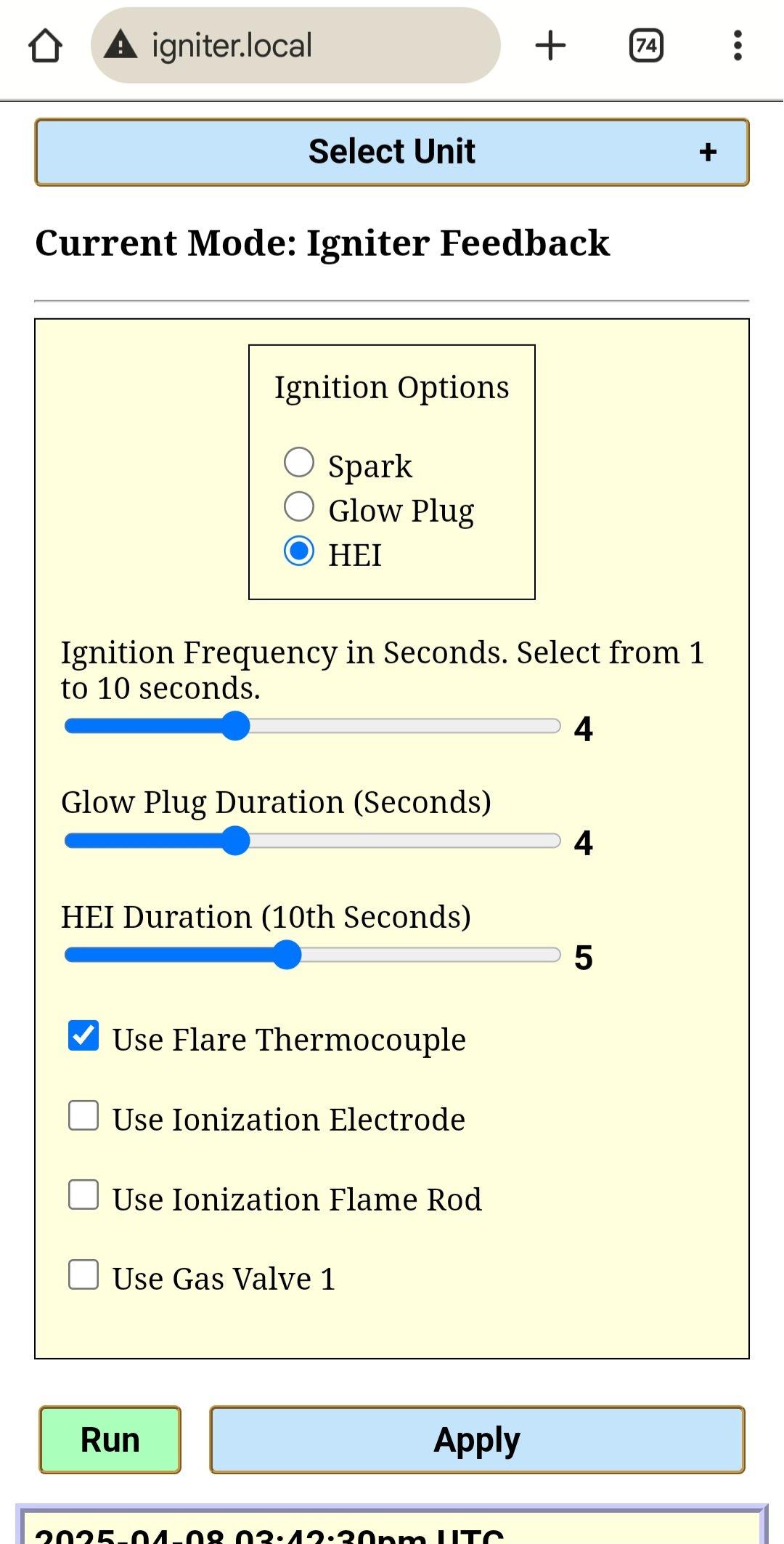
Flare Igniter with FeedbackIgnition Type:The BMS is configured for HEI ignition, suitable for flares, with adjustable pulse length (e.g., 0.4 seconds for a setting of 4 tenths).Flame Sensing:Operators choose from multiple igniter feedback options for flame verification, which can be used singly or in tandem for a redundant system.Thermocouple:Detects flame with a threshold met at 300°F for verification.Ionization:Uses an flame rod to sense flame at the pilot.Ignition Rod:Senses flame through an ignition rod at the flare pilot.Valve 1 Selection:Operators can select Gas Valve 1 to control the pilot fuel source if desired, ensuring precise gas flow to the flare pilot.Customization:The BMS can be tailored to specific flare requirements, such as unique ignition timing or sensor configurations, to meet operational needs.Security:The default Wi-Fi password is changed during setup to prevent unauthorized access.Flare IgnitionActivation:When an automated command is issued, the BMS energizes the HEI ignition system to create a spark at the flare tip.Gas Valve Control:The BMS opens Gas Valve 1, the designated valve for flare operation, to allow gas flow, controlled by solenoid states (e.g., HI/LO for open, allowing gas flow).Feedback:The BMS monitors ignition attempts (tracked via Ignition Tries) and flame detection status (e.g., Flare Flame Rod at 100% indicates a successful flame).Real-Time MonitoringLive Readings:
Full Smartphone DisplayThe BMS provides real-time diagnostics, including:Flame Rod Ionization Flame detection. Will be 0% if there is no flame or 100% if flame.Temperature readings using a Type-K Thermocouple. Flame TC Temp, if used will display the temperature or if not connect it will display Ground-short or not connected. Gas Valve 1 status (e.g., Valve 1:LO,FB:HI indicates solenoid is functioning). System alerts (e.g., [Pilot Electrode may be Defective] if issues are detected). Interface: Operators view these metrics on the intuitive, single-page display at igniter.local, with LED indicators (Red:Ignition, Green:Flame, Blue:No Flame) and GPS status for setting Time, Date, and tracking location. Pilot Monitoring:The pilot monitoring system provides continuous updates on pilot flame status, ensuring reliable operation.Safety and Emergency ShutdownFlame Detection Failure:If flame sensing (e.g., thermocouple or ionization) indicates no flame (e.g., Flare Flame Rod Ion: 0%), the BMS halts gas flow by closing Gas Valve 1 to prevent gas buildup.Emergency Shutdown (ESD):Operators can press the [ESD] button on the interface to shut down the flare, and press the [Run] to start.Alarm Thresholds:Adjustable alarms notify operators of issues like defective sensors or solenoid faults, i.e.
Safety Features:The BMS ensures compliance with local electrical regulations and uses robust enclosures to withstand harsh conditions.Troubleshooting and MaintenanceRegular inspections:Check wiring for corrosion, and firmware updates are applied via USB-C by ROS technicians. Sensor calibration is performed through the UI.Alerts:System alerts (e.g., defective pilot electrode) initiate troubleshooting, with support available by clicking contact.Key FeaturesMade in America:As one of the only U.S.-made controllers, the ROS BMS guarantees a secure supply chain, supporting uninterrupted oilfield operations.First in Permian:The Wi-Fi-enabled BMS is a pioneering solution in the Permian Basin, setting a new standard for remote flare control.Convenience:Operators control the flare remotely from a vehicle or office, reducing exposure to hazardous conditions.Efficiency:Instant adjustments via the Wi-Fi interface optimize flare performance.Precision:Fine-tuned ignition and flame detection settings, with a 300°F default threshold for thermocouple sensing, ensure accurate operation.Safety:Secure connectivity, emergency shutdown, and real-time diagnostics enhance safety.Customization:The BMS can be tailored to specific flare requirements, ensuring optimal performance.Pilot Monitoring:The pilot monitoring system provides continuous updates on pilot flame status, enhancing operational reliability.Flexible Flame Sensing:Multiple igniter feedback options (thermocouple, ionization, ignition rod) allow single or redundant flame verification, with Valve 1 selection for precise pilot fuel control.ConclusionROS BMS is the first Wi-Fi-enabled flare controller in the Permian Basin, offers a robust, American-made solution for oilfield flare management. By integrating Wi-Fi connectivity, precise ignition control via Gas Valve 1, real-time monitoring with a pilot monitoring system, flexible flame sensing options, and customization capabilities, it ensures safe and efficient flare operation. Regular maintenance and adherence to the manual's guidelines maintain compliance and reliability, positioning operators as industry leaders.
|
Igniter with Feedback
|
CombustorROS BMS Combustor
|
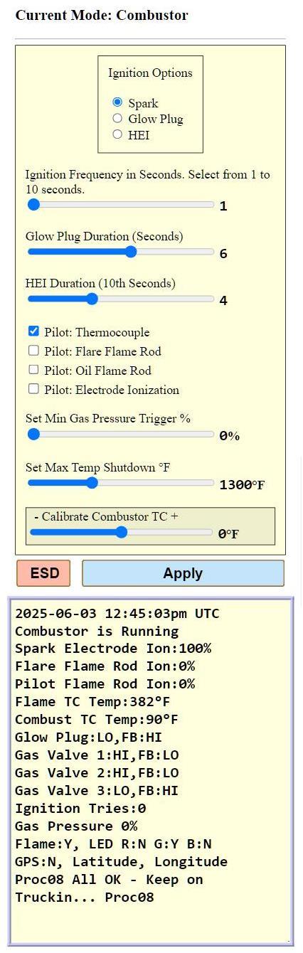
Combuster
Full Smartphone Display |
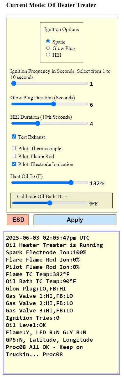
Oil Heater TreaterROS BMS Oil Heater Treater Control DescriptionOverviewThe Reliable Oilfield Services (ROS) Burner Management System (BMS) is a Wi-Fi-enabled controller designed to manage heater treaters in oilfield applications, proudly Made in America. As one of the only American-made and manufactured controllers, it ensures a reliable supply chain, supporting operational continuity. The BMS, the first Wi-Fi-enabled system of its kind in the Permian Basin, provides remote monitoring and control via a smartphone, tablet, or laptop, enhancing safety, precision, and efficiency. The unit can be customized for specific heater treater requirements, ensuring tailored performance for diverse oilfield needs.Key Components

Control Process
Functionality:To determine whether a gas valve is functioning correctly, monitor its status based on the following expected readings, i.e.Each reading consists of two parameters:
Key Features
ConclusionThe ROS BMS, the first Wi-Fi-enabled heater treater controller in the Permian Basin, offers a robust, American-made solution for oilfield heater treater management. By integrating Wi-Fi connectivity, precise ignition control with selectable methods (HEI, ignition coil, or glow plug) using Valve 1 for fuel supply and safety shutdown, pilot ignition via Valve 2, main burner activation via Valve 3 after a 15-second flame stabilization period using selectable ionization rod, ionization flame rod, or thermocouple, real-time monitoring through designated board spots (Pilot Status Terminals and Oil Status), thermocouple-based temperature control with an optional 1100°F high-temperature safety shutdown via the exhaust stack thermocouple, oil bath level protection via the level switch with a shutdown after five failed ignition attempts requiring manual ESD clearance, and customization capabilities, it ensures safe and efficient heater treater operation. Regular maintenance and adherence to the manual's guidelines maintain compliance and reliability, positioning operators as industry leaders. |
Oil Heater Treater
Full Smartphone Display |
ROS BMS Q&AWhat are the Electrical and Grounding Best Practices?
Burner Management System Q&A
Waste Gas Flare Stake Igniter BMS Q&A
Combustor Incinerator Igniter BMS Q&A
Oil Heater Treaters Separate Oil-Water-Gas Q&A |
Artificial Intelligence BMSDefining AI BMS:Artificial Intelligence (AI) refers to the simulation of human intelligence in machines that are programmed to think and act like humans, mimicking cognitive functions such as learning, reasoning, and problem-solving. Essentially, it's the ability of computer systems to perform tasks that typically require human intelligence.Let the SmartPhone BMS App put its AI to work on your behalf. Simply use your computer or smartphone to tell it what you want, and the AP SmartPhone BMS's built-in WiFi Access Point (Wi-Fi AP) Server will carry out your Burner Management System plan; whether it is controlling a waste gas flare stack ignition system, combustor, or oil heater treater. |
More intresting pictures